简介
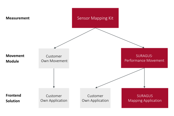
EddyCus® map IK是一款由三个模块组成的测绘集成套件。其核心是包含传感器、测量电子设备和控制单元的传感器套件。根据客户需求,系统可配置为传输模式(样品上方和下方各放置一个传感器)或反射模式(单个传感器置于样品上方或下方)。应要求,传感器套件可集成至现有运动系统,或与SURAGUS专属运动解决方案组合使用。采用SURAGUS方案时,可直接使用预装软件模块,该模块已包含高级测量功能、配方管理及预定义运动控制。客户亦可自主开发软件,此时运动控制通过PLC系统的OPC UA接口实现,测量电子设备则通过REST API进行访问。可选模块如下:
- 基础模块 – 传感器映射套件
- 运动模块
- 现有客户运动系统
- 苏拉格斯表演运动
- 软件模块
- SURAGUS MAP Core 平台的客户定制化集成
- 苏拉格斯地图应用程序
高频涡流测绘解决方案,实现对片电阻、电阻率和导电率的非接触式测量。选择最适合您应用需求的集成级别。
在此处添加您的工具提示文本
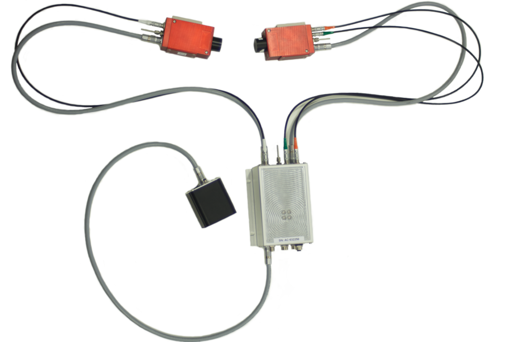
MAP IK 传感器映射套件(仅套件)
EddyCus® 地图IK传感器测绘套件是一款不含任何运动硬件的纯传感器套件。该套件基于非接触式涡流传感器,特别适用于表征导电层与基材,包括:
- 面电阻值范围:0.05毫欧姆/平方至300,000欧姆/平方
- 导电层厚度从1纳米到100微米
- 电阻率范围为0.1至1000毫欧姆·厘米
根据您的需求,提供三种配置方案
- 传感器间隙可达25毫米的传输模式
- 反射模式
- 顶级传感器配置,特别适用于保龄球
- 底部传感器配置,特别适用于冰球
传感器可通过多种安装选项集成至您现有的测绘系统。STEP数据可应要求提供。
若您尚未配备运动平台,可通过以下章节了解我们高性能运动平台的更多信息,或直接联系我们获取其他解决方案。
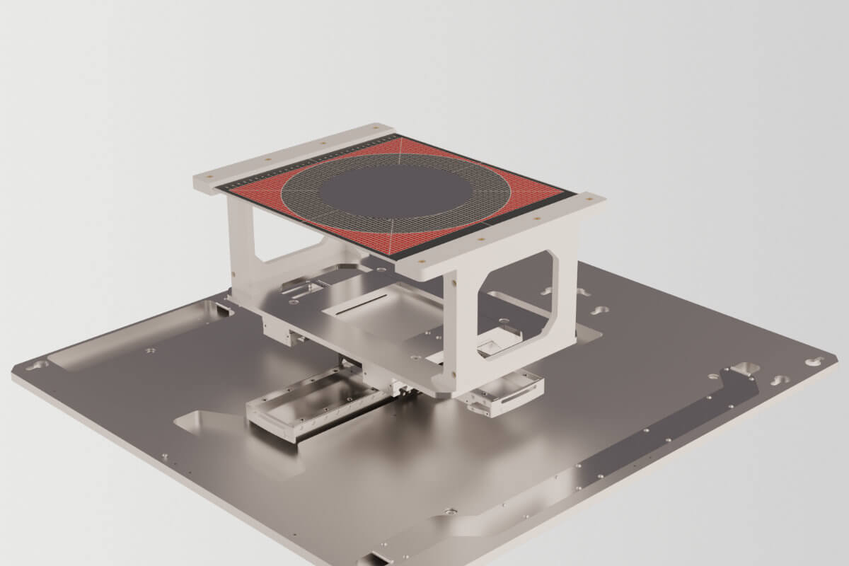
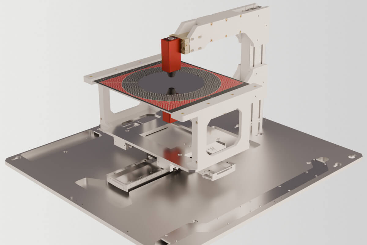
苏拉格斯运动模块
映射集成套件的高性能运动模块
高性能测绘平台版本是速度与测量性能方面的极致解决方案。
| SURAGUS High Performance Movement | |
| Technology | Linear motors |
| Position Precision Feedback | Very High |
| Edge Exclusion | ≤1 mm |
| Movement Speed | Up to 600 mm/s |
| Initalization Process | Instantly ready to scan (no homing process necessary) |
| Axle Movement | Synchronious movement of x and y axis |
| Scanning Path | Complex but efficient paths are possible (due to synchronious movement) |
| Maintenance | Practically no maintenance (lubrication every 500,000 km) |
| Reflection Mode Accuracy |
±2 % via lift off compensation
±1 % through active piezo distance adaption |
SURAGUS 测绘集成软件套装
SURAGUS测绘集成软件套件是先进涡流测绘的核心软件平台。它涵盖从数据采集到可视化的完整工作流程,并能轻松将SURAGUS系统集成到现有环境中。
- SURAGUS 测绘集成软件套装包含
- SURAGUS MAP 核心驱动程序
- 从SURAGUS传感器测绘套件获取测量数据
- 处理数据,例如执行EEC评估或推导电阻率等次级参数
- 足以运行您自己的应用程序
- 可选SURAGUS测绘应用程序
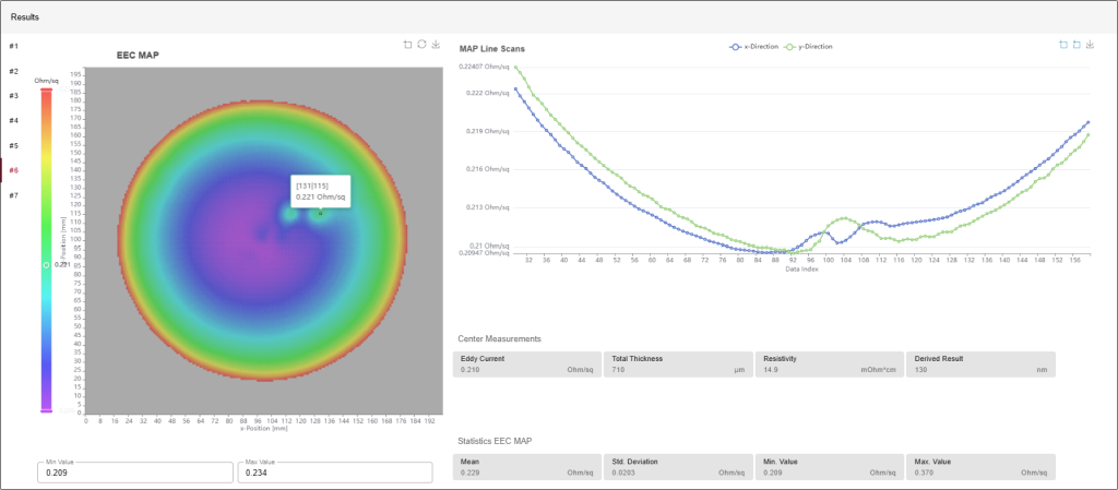
- 在直观的前端界面中可视化测量结果,包括详细地图和统计数据
- 该应用程序采用现代Python代码实现,并设计为可支持未来扩展。它已支持
- 使用基恩士共聚焦传感器进行二维TTV评估
- 集成您自己的次级软件开发工具包(SDK)
- SURAGUS测绘应用程序为系统集成提供了REST API接口。这使得更高层级的系统能够触发测量任务、获取测量结果,并将SURAGUS数据直接嵌入现有过程控制或质量管理解决方案中。
- SURAGUS MAP 核心驱动程序
Map IK Sensor
Sensor Only Variant-
涡流传感器
-
Control Unit
-
Wafer, Pucks or Boules
-
REST-API Interface
-
Movement System
-
Complete Frontend Solution
send Request
Ideal solution who want extent existing map tools with eddy current measurements
Map IK – Performance
Sensor + Performance Movement-
涡流传感器
-
Control Unit
-
Wafer, Pucks or Boules
-
REST-API Interface
-
3-Axis Linear Motors
-
Highest Speed (≤ 600 mm/s)
-
Best Edge Exlusion (≤ 1 mm)
-
Smart Scanning Paths
-
Instant Measurement without Homing
-
Complete Frontend Solution
send request
Ideal solution for companies that need a complete hardware solution with best measurement capabilities.
Best Choice
Map IK
Complete Turnkey Solution-
涡流传感器
-
Control Unit
-
Wafer, Pucks or Boules
-
REST-API Interface
-
3-Axis Linear Motors
-
Highest Speed (≤ 600 mm/s)
-
Best Edge Exlusion (≤ 1 mm)
-
Smart Scanning Paths
-
Instant Measurement without Homing
-
Complete Frontend Solution
send request
Ideal solution for companies that need ready to go a complete hardware and software solution.
Min Effort
Data Table for EddyCus® map IK
Sensor Mapping Kit – Measurement Capabilities
| Transmission mode sensor setup | |
|---|---|
| Sheet resistance measurement range | 0.05 mOhm/sq – 300,000 Ohm/sq | Reflection mode sensor setup |
| Resistivity measurement range | 0.1 – 1,000 mOhm·cm |
| 电导率测量范围 0.01 - 65 MS/m | |
| Sheet resistance measurement range | 0.05 – 100 Ohm/sq | General features |
| Calibration package | A variety of sheet resistance or resistivity reference standards are available at SURAGUS |
| Encoder input |
ASU Gen1 case: NO
ASU Gen2 case: up to 3x (A/B/Z) via internal Trigger Board |
| TTL | ASU Gen1 case: 2x Trigger count + Reset Edge Mode for PTP-applications Trigger rate up to 3kH |
| Software trigger | Included |
| SURAGUS MAP Core |
Path planing PLC module
Rest-API to SURAGUS MAP Core OPC UA or others to PLC SECS GEM (E30) |
Movement Features
| Standard Movement | Performance Movement | |
| Base plate | Stable table with a maximum scanning area of 320 x 320 mm base plate ensures mechanical rigidity, and an integrated electronic board behind the actuators hosts the electronic components An optional third axis enables motion in the z direction. This is particularly useful for RMT versions and is available either as a simple z axis or as a closed loop controlled axis for automatic distance adjustment during reflection mode scans. | |
| Housing | No housing included | |
| Location of electronic components | On e-board behind actors | |
| Measurement IPC | ASU control unit to run optional application front end | |
| Number of axis | Up to 3
third axis enables motion in the z direction. This is particularly useful for RMT versions and is available either as a simple z axis or as a closed loop controlled axis for automatic distance adjustment during reflection mode scans.
|
|
| SURAGUS Movement Modules | PLC code included | |
| SURAGUS MAP Core |
OPC UA or others to PLC
SECS GEM (E30) |
|
| Secondary measurement methodologies | Customer integrated secondary SDKs | |
| Substrates | Wafer, pucks and boules with 2 inch – 300 mm diameter | |
| Technology | Stepper motors | Linear motors |
| Position Precision Feedback | High | Very High |
| Edge Exclusion | 3 – 5 mm | ≤1 mm |
| Movement Speed | Up to 150 mm/s | Up to 600 mm/s |
| Initalization Process | Homing process for each imaging | Instantly ready to scan (no homing process necessary) |
| Axle Movement | Sequential movement of x and y axis | Synchronious movement of x and y axis |
| Scanning Path | Simple meander mode | Complex but efficient paths are possible (due to synchronious movement) |
| Maintenance | Lubrication once a year | Practically no maintenance (lubrication every 500,000 km) |
| Reflection Mode Accuracy | ±3 % via lift off compensation |
±2 % via lift off compensation
±1 % through active piezo distance adaption |
| Performance Movement | ||
| Base plate | Stable table with a maximum scanning area of 320 x 320 mm base plate ensures mechanical rigidity, and an integrated electronic board behind the actuators hosts the electronic components An optional third axis enables motion in the z direction. This is particularly useful for RMT versions and is available either as a simple z axis or as a closed loop controlled axis for automatic distance adjustment during reflection mode scans. | |
| Housing | No housing included | |
| Location of electronic components | On e-board behind actors | |
| Measurement IPC | ASU control unit to run optional application front end | |
| Number of axis | Up to 3
third axis enables motion in the z direction. This is particularly useful for RMT versions and is available either as a simple z axis or as a closed loop controlled axis for automatic distance adjustment during reflection mode scans.
|
|
| SURAGUS Movement Modules | PLC code included | |
| SURAGUS MAP Core |
OPC UA or others to PLC
SECS GEM (E30) |
|
| Secondary measurement methodologies | Customer integrated secondary SDKs | |
| Substrates | Wafer, pucks and boules with 2 inch – 300 mm diameter | |
| Technology | Linear motors | |
| Position Precision Feedback | Very High | |
| Edge Exclusion | ≤1 mm | |
| Movement Speed | Up to 600 mm/s | |
| Initalization Process | Instantly ready to scan (no homing process necessary) | |
| Axle Movement | Synchronious movement of x and y axis | |
| Scanning Path | Complex but efficient paths are possible (due to synchronious movement) | |
| Maintenance | Practically no maintenance (lubrication every 500,000 km) | |
| Reflection Mode Accuracy |
±2 % via lift off compensation
±1 % through active piezo distance adaption |
|
SURAGUS Mapping Application Addon
| Compatible with | SURAGUS Performance Movement Module |
| Measurement acquisition | Included |
| Data processing |
Edge effect compensation algorythm (EEC) included
Derive other measures like resistivity |
| Display data | Front end |
索取报价
您可以使用此表格给我们留言。